Fab challenge 1
The first Fab challenge revolved around 3D CAD. With Blender as free, open-source software that could be applied to a wide range of (professional) applications. In none of my previous designwork have I encountered Render being applied before. In fact I only knew it from character design for a while but only really thought of it recently as it gained more exposure in the world of NFT's.
References
Webpages from MDEF-alumni in the past recent years that interested me the most were those of Pietro (2020-21), Jessica (2018-19), and Fífa (2018-19). I tried using elements of their compositions, style and features in my pages.
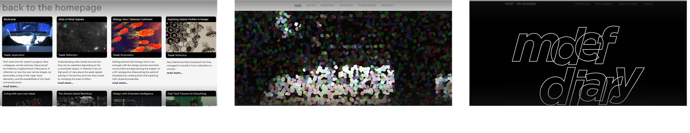
Pietro's logical box-structured layout on his github website used integrated artwork in a clear grid on both desktop as well as mobile. In this website I adopted this idea for my sub-menu's. Jessica's website had some recognizable (PS-)effect applied in a animation.
CAD
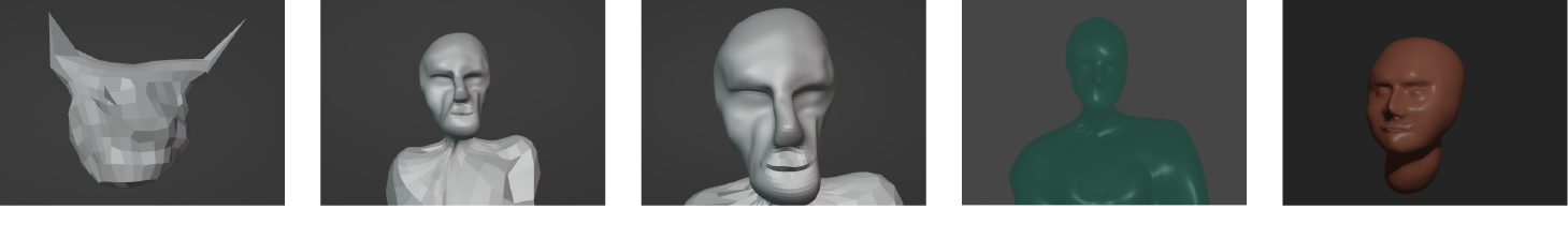
Eduardo gave us a brief overview on the history of CAD and how it came to life as a tool for efficiency. He explained us the theory behind vector- and pixel-based graphical software and the important distinction (export file types, interoperability) between the two. Viktor displayed the workspace of Blender, offering loads of opportunities for digital sculpting, animation, AR, texturing and rendering.
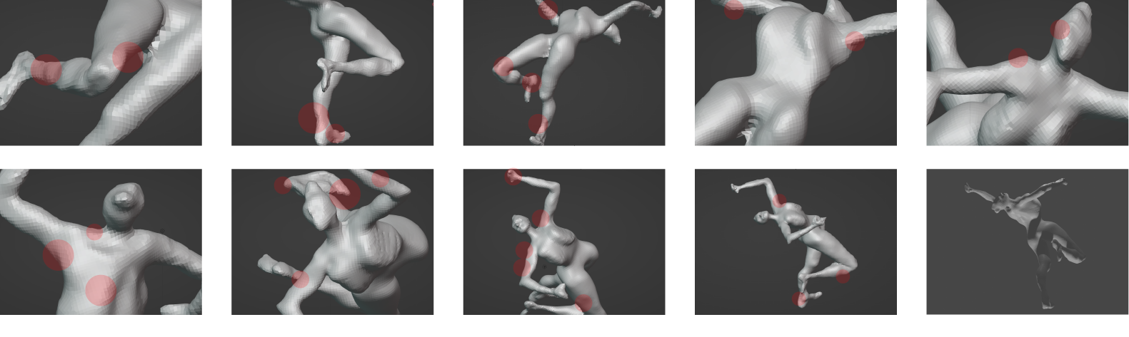
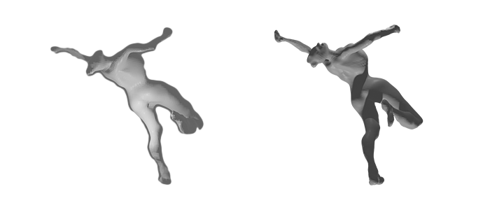
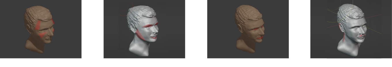
I wanted to explore the sculpting feature-section in Blender since we had the idea running to integrate biomaterial in sculpted objects.
3D printing
FDM printing
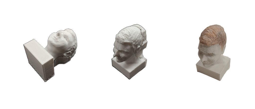
After a few itereations the CAD model was printed in PLA with a FDM (= Fused Deposition Modeling)-printer. The first attempt lacked support resulting in bad geometry. Adjusting the slice-settings in Cura 3D slicing/3D printing software generated a workable G-code for the FDM-printer to run for about 70 minutes.
CAM
Laser cutting
The second seminar and week of Fabacademy Local is centered around Computer Aided Machining (CAM). As main topic CAM can be divided into additive and substractive manufacturing. Josep explained a timeline on how this technology developed from the first versions of laser cutters in the 50's to the modern day CO2 laser (light amplification by stimulated emission of radiation) cutters. An example of substractive manufacturing is fabricating in Computer Controlled Cutting. In this the input device generates a G-code which defines shapes and figures in 2D as lines of code. This is send to the controller of a laser cutter which on its turn provides signals to both the laser source that sends the laser through the optics (lens plus three mirrors) onto the material as well as the XY-axis controlled CNC. Aside of these axis the remaining adjustable parameters are the power, speed and frequency (PPI: pulses per inch) of the laser, the control of the air compressor and the specifications of the lens. By adjusting these parameters the desired result of running the program can vary between either engraving lightly of cutting through the material. By categorizing cut- and engraving orders into different colored layers both functions can be applied on the same product.
The most common laser cutters are CO2 based. They are relatively cheap and accessible in terms of purchase and finding spare parts. Neodymium-based laser cutters are more industrial aimed. Opposing to CO2 cutters, Fiber cutters are able to cut metals.
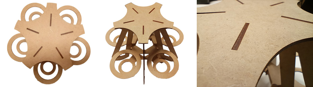
By unfolding a existing 3D shape in CAD to a 2D lasercut-suitable file - for example .dxf - laser cutters are indirectly able to generate complex 3D shapes. Important feature in this is correctly applied nesting. With the purpose of creating as less residu material as possible while using the right tolerances and taken in account the machine's kerf and material properties. Common materials are cardboard, plywood, acrylic and MDF (Medium Density Fibreboard: duo-directional resined layered wood).
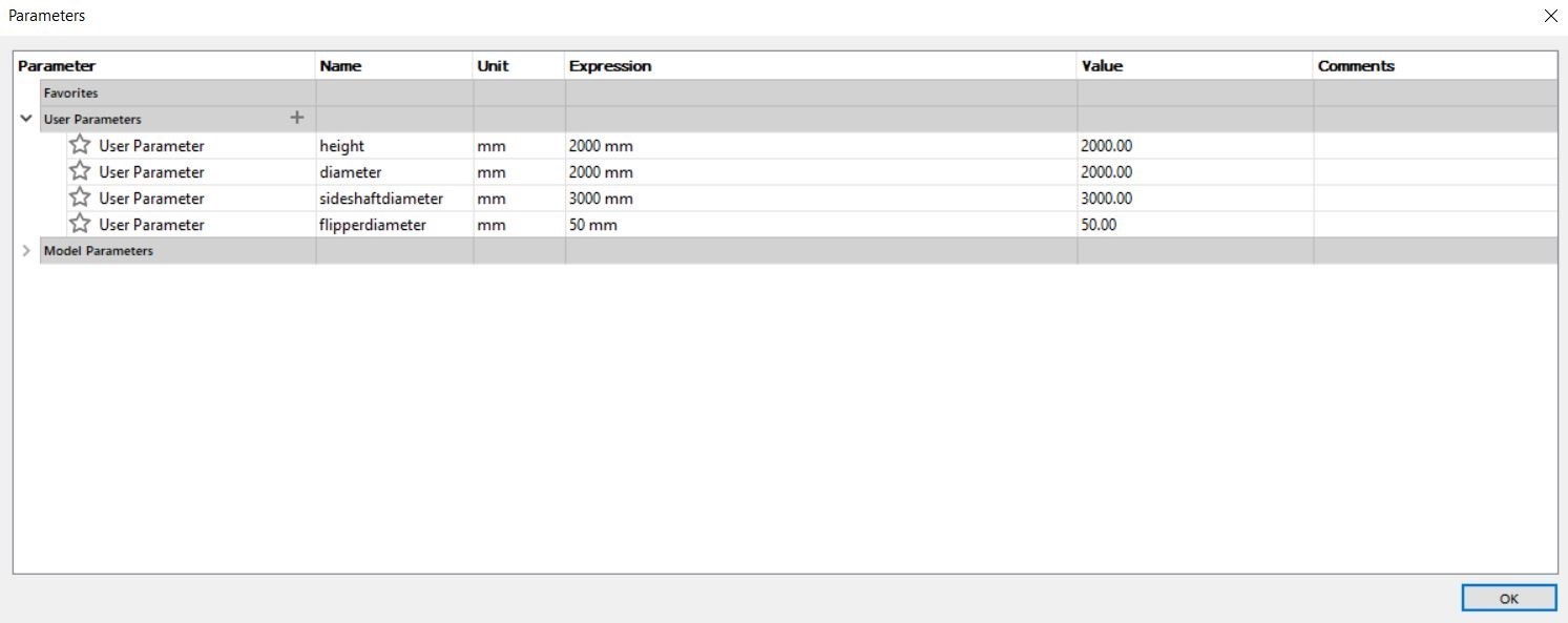
Parametric design
Using a systemic methodology in which certain given parameters result in the adjustments of features of a spacial object is called parametric design. In software(plugins) such as Grasshopper, Autodesk Maya, Blender and Fusion 360 parametric design can be applied for various reasons. It can be used when a quick customization of an assembly is desired in for example the production of prostheses, 3D-printed objects, souvenirs or jewellery.
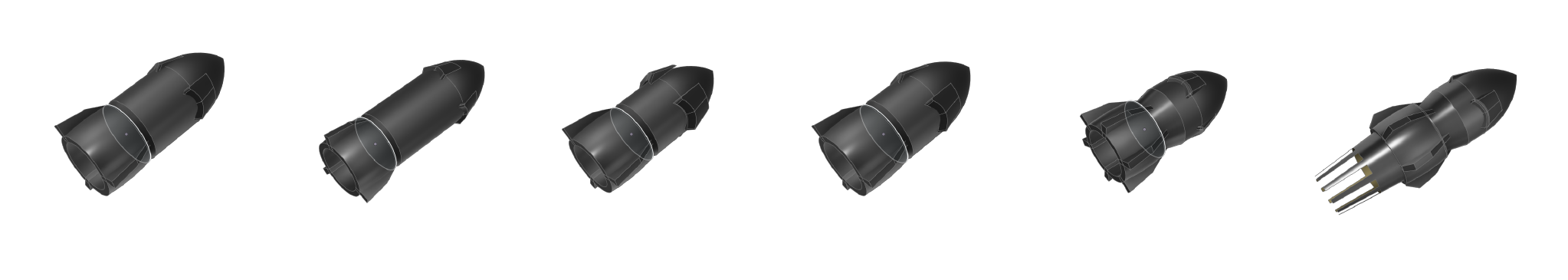
The rocket hints at the rich opportunities and capabilities parametric design brings when using variable design.
For project Duckweed I drew and exported an assembly of a PET tray in Fusion. The tray can hold five 1.5 liter PET bottles in which duckweed samples can grow. I tailored the tray to the diameters of the center, neck and cap respectively.

Electronic Production
PCB
We use PCB's (=Printed Circuit Board) instead of wired electronic circuitry for several reasons, the main ones are the size-reduction and ability to move. Considering the former, in the recent years the technology has become extremely precise. SMD's (=Surface Mount Device) function with a width of 0.3 mm. with 0.1 to 0.2 mm copper layers. The most common PCB's are made of FR4 (a composite material of epoxy resin and glass fabric with layers of copper) whichare protected with a solder mask.
Two new technologies that are emerging from the field of electronics design are 3D printable conductive materials to create custom electronics embedded in 3D (e.g. PLA) printed objects. One high-tech technique of creating circuitry is via LDS (=Laser Direct Structuring). During this a laser engraves the circuitry onto an 3D object. After an hour of explanation and historical overview on Printed Circuit Boards Eduardo invited us to solder a small circuit.
Soldering
Flux is the synthetic resin that serves as agent for a smooth solder connection. Different solder irons (40/60/80 watt) determine different worktempos and heating abilities. The solder used is either with or without lead.
Mods Project
Josep explained the Mods project as steering software for the CNC cutter available at FablabBcn, the SRM-20 mill.