Fab challenge 2
The second Fab challenge focussed on fabrication and production. Touching on the topics electronic production and computer controlled machining.
Electronic components
Eduardo gave a short description on electronic components starting off with types of resistors including voltage dividers, pull-up and pull-down resistors. Examplary applications with large capacitors are audio-amplifiers, hi-fi equipment, subwoofers.
Capacitors can be seen as 'instant-batteries' for their ability to store electrical energy in an electric field. Generally their negative poles are marked in white. Adapters such as phone chargers do not generate a fully stable constant voltage output. For this reasons capacitors even out the electric current.

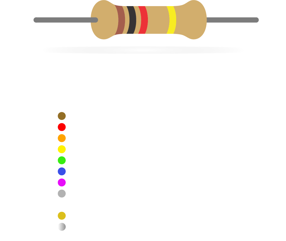
Diodes Led's (=Light Emitting Diode) have a emitting Anode (+) and a receiving Cathode (-) meaning their current can only flow in one direction.

Oscillators are components that generate a periodic signal. Depending on the desired usage their frequency can vary largely. Their signalling is regulated in either sine waves, square waves or triangle waves.

Mosfet's and transistors are similar components. A transistor works as a power gate. Compared to Mosfet's transistors are faster but more sensitive. Therefore Mosfet's are better when applied to more power-demanding and in higher variations of voltage applications, while transistors are better applied in time-sensitive uses.

Regulators a DC linear voltage component that regulates the output voltage even when the supply voltage is very close to the output voltage.

The features and detailed specified information of individual electronic components are inventarized in datasheets as can be found on websites of large distributors such as Digikey.
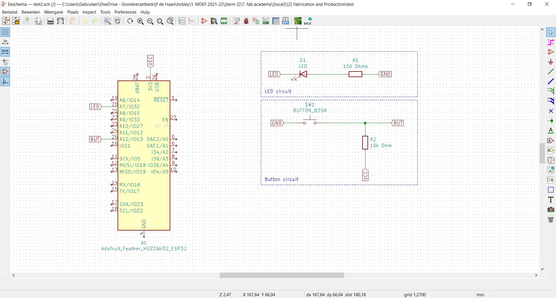
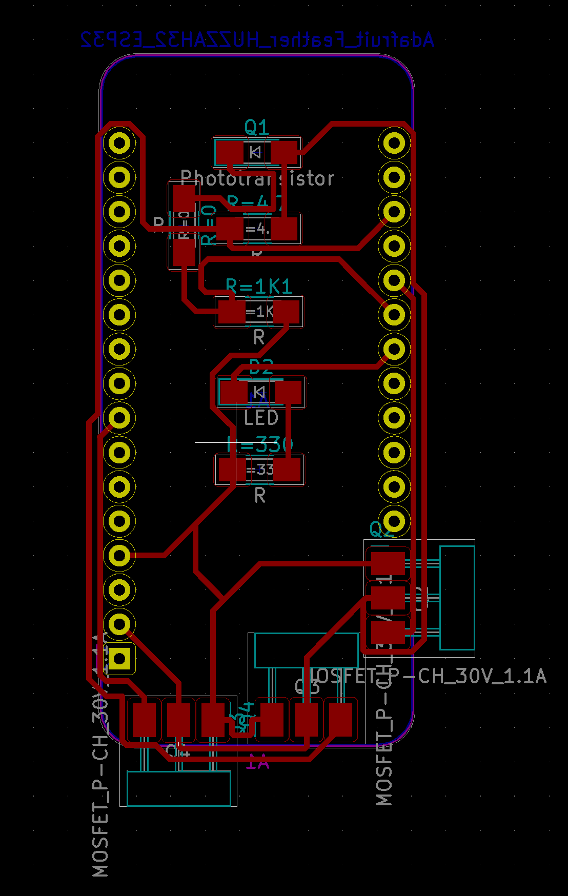
Applying these components in an context KiCad can be used as an open-source EDA (or ECAD= electronic computer aided design) software and tool to design electronic systems. Josep forwarded us some libraries with popular PCB configurations which can be found on KiCad.
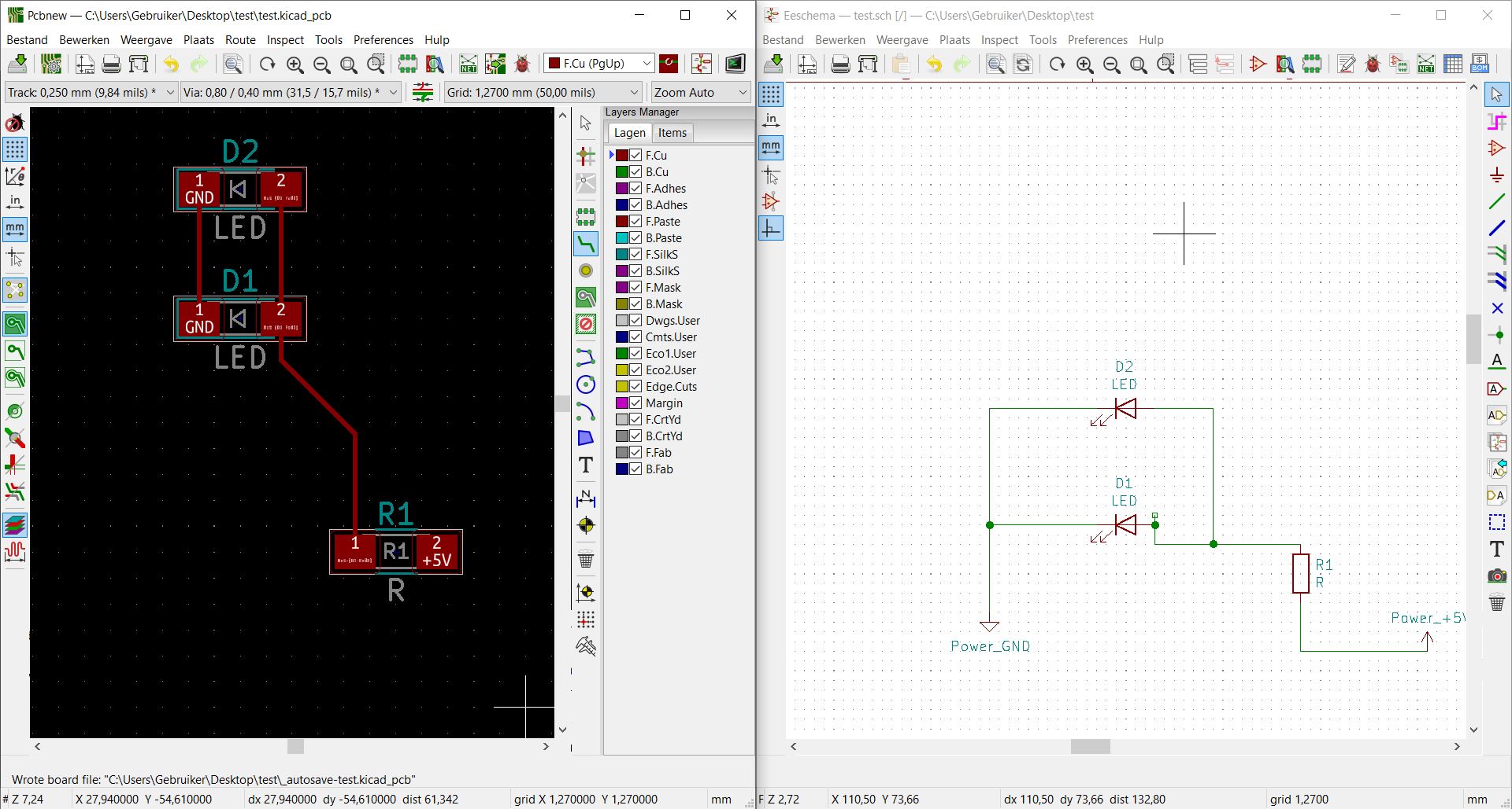
With the 'fab.pretty' and additional libraries installed we drew and tagged our first sketch including a Adafruit Feather ESP32.
Computer Controlled Milling
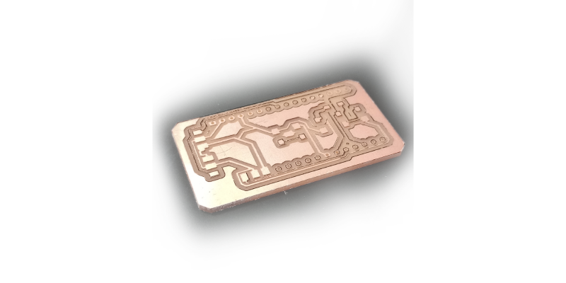
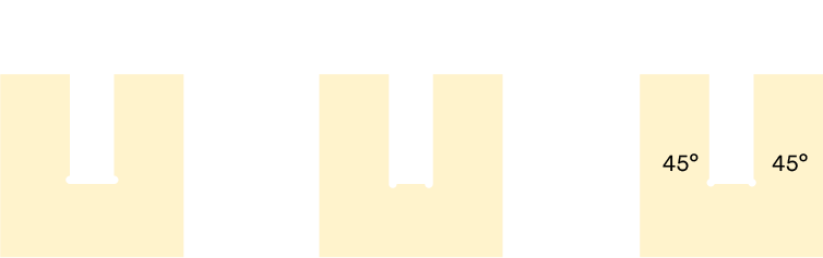
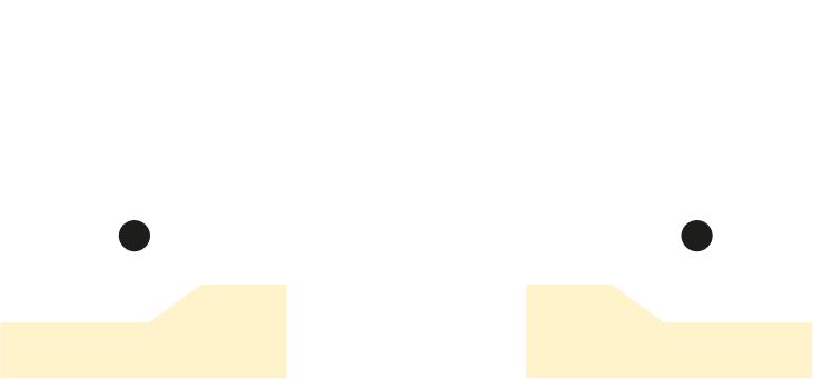
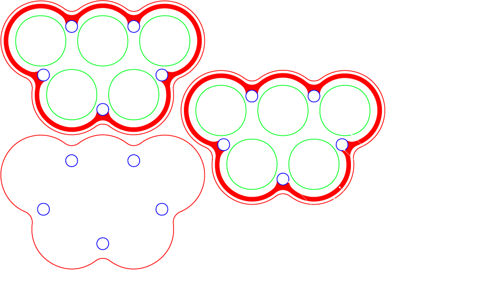
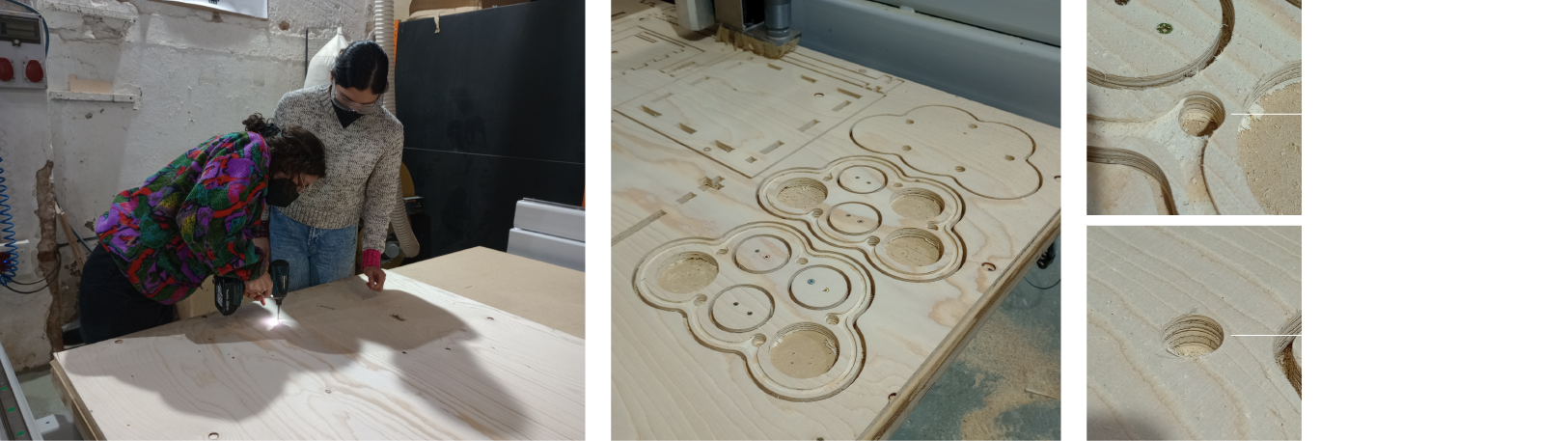
Theory of CCM started off with Eduardo explaining how the workflow of designing and manufacturing in CAD has not change much since Boeing started its principle in the late 1960's. Easel CNC software. In CNC milling the process starts with a large volume which is substracted by a two axis fast rotating drill. In a five (+) axis CNC milling machine the product itself is CNC coordinated as well. The main reasoning for Computer Controlled Milling is automation. Repeatability is an important factor in mass production of CCM and means its variation in trying to create an identical result multiple times. All machines have a certain accuracy which reduces over time due to wear (stretch in the timing belts and/or wear of the cutting bits). The motor that holds the cutting bit is either a common, relatively cheap and upgradable router or a quiter, more powerful - but expensive - spindle. Due to the cutting bit's diameter sharp (90°) internal angles are not feasible. Straightcut (±20€ pp), upcut (±30€ pp), downcut (±60€ pp) and compressed cut (±100€ pp)
Easel is a CNC-software from Inventables. Josep gave an explaination on setting up a file imported from Rhino.
-
Specifications included:
- Feed rate: 3800 mm/min
- Plunge rate: 2000 mm/min
- Depth per pass: 3 mm
- Spindle speed (RPM): 18000
This results in an ouput as G-code that can be read and executed by the CNC-cutter.

Computers
'How to make a computer'. Viktor presented us an introduction to digital electronics by first downsizing this concept to a mechanical computational system. Instead of perceiving a computer as a magical black box, we can understand its functionality as combined calculations. Viktor explained the main difference between analog and digital as continuity. Analog output data is fluid while digital output data is discrete/distinct. (combined) Transistors allow combinational circuits that give certain output at a specific input. Their main functionality in this is to multiply or switch. With transistors storing a certain state creating electronics with a 'memory'. Through the years technology precisioned allowing to have these transistors on nano scale creating microcontrolling chips.
Combining these into more and more complex systems creates electronic architecture on smaller and smaller scale. The commodor 64 released in the 90's had 64.000 bits of memory (i.e. transistor functionalities).
A few decades later the Raspberry Pi Zero (released in 2017) allows 512.000.000 bits (512MB) of memory throught its SoC (=System on a Chip). The main difference between operating a PC and programming a Arduino is the lack of a managing operative system (e.g. iOS, Windows, Linux) on the latter. Programming a Arduino is more direct therefore (bare-metal). Computational functions work in loops. The clock speed of these circulations is defined in Hertz. In modern computers quartz crystals create these frequencies.
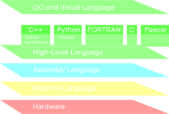
From ideas to code. If one wants to transform an idea to hardware there are several layers one has to pass through.
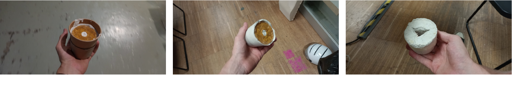
Molding and Casting
Molding is a ancient craft that has been executed for centuries stretching back to 20.000 BC ancient China. The main objective of making molds is to create a negative shape of a positive model (which can be replicated). Applications vary from juwelery, prosthetics, prototyping, dental- and industrial applications. Molds can be designed and fabricated analogue, digital or a hybrid form. Rotational casting is a common applied subclass of casting where the melted material is rotated on the walls of the mold creating a hollow product.
3D milling
After having worked with the 2.5D milling (Variable X and Y axis and stepped Z-axis). In 3D milling this process is divided in three steps (rough cut flat, rough cut round, finish cut round) the first rough cut removes the largest portion of the negative of the product, followed by the rounded rough cut to define the shape more and finished by a rounded finish cut that 'polishes' the detailed final product. The realised mold needs to be treated by a coating or realease agent to prevent the product from being porous/sticking to the mold. This product is usually made by mixing two components that need to mixed fully.
Examples of materials that can be CNC milled to create a mold are machinable waxes (various shorenesses, surface finishes, detailing etc.), latex, resins, silicons and wood types. Wax per definition is self-lubricating, softer, more homegenous and less-stressing compared to wood.