Drone
Recently I came across the CircuitMess Wheelson on the Arduino website and got the idea to initiate a setup for a Arduino drone. Since there is plenty of information on the topic on numerous blogs, online communities and webshops, creating the concept of the hardware turned out not to be difficult with plenty of references available online.
Timeline:
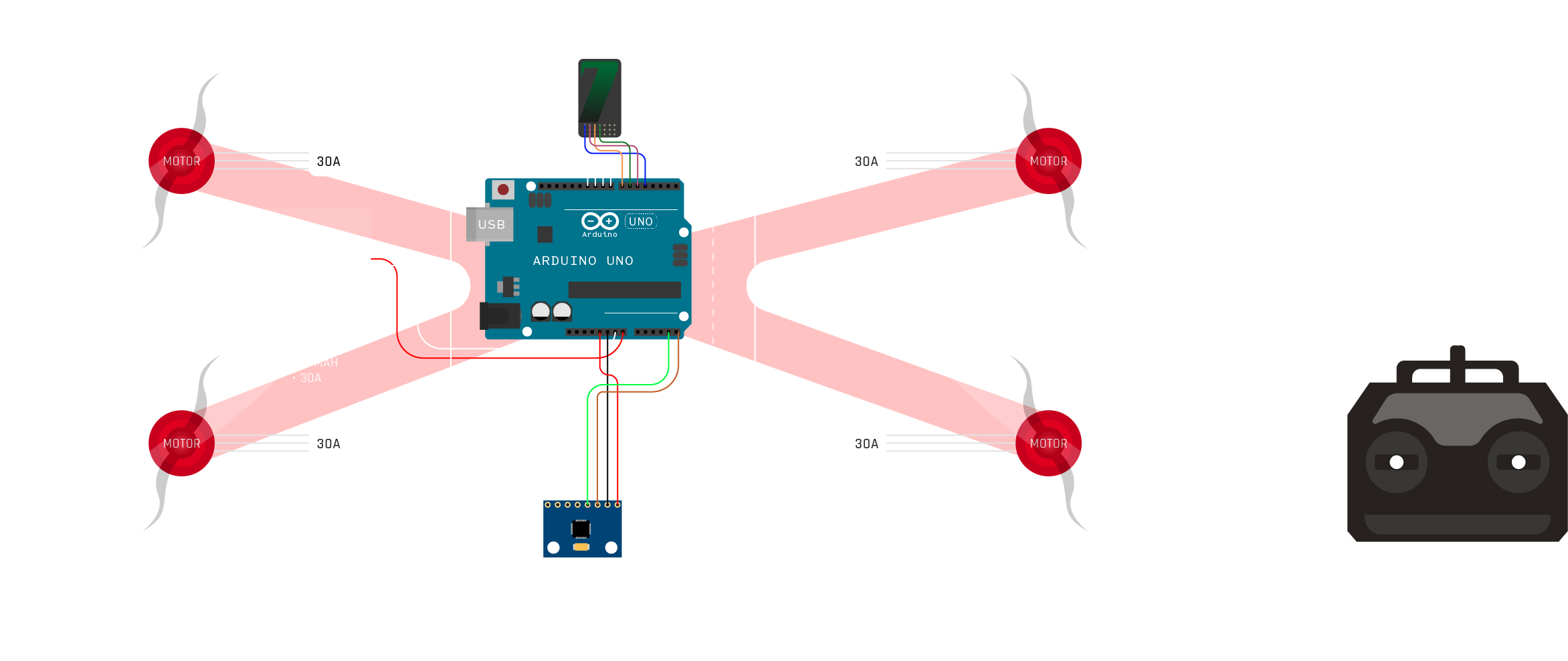
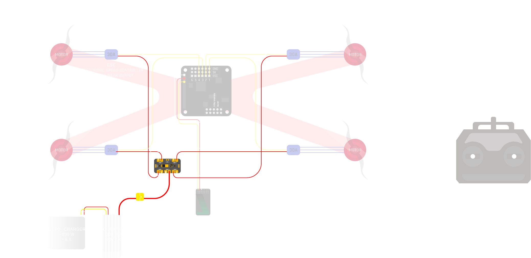
- October 21: First circuitry setup.
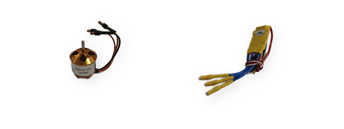
- October 21: Functional test failed of first quarter of the ESC/rotor/motor assembly.
- December 21: Frame, RC-transmitter and RC-receiver inventarized.
- March 1: Discussion with Eduardo on initial soft- and hardware setup.
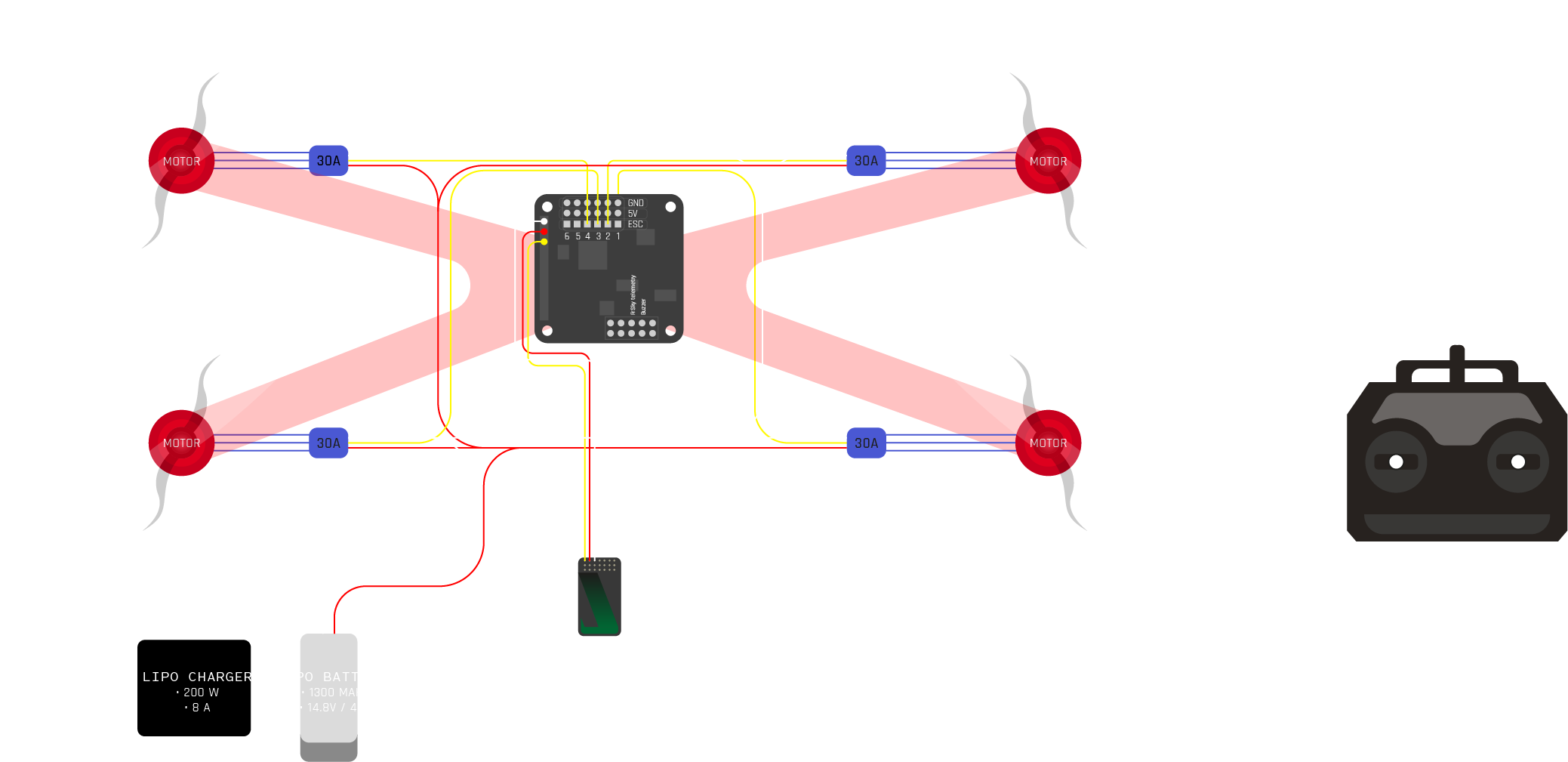
- March 6: Second circuitry setup.
- March 8: Functional test failed of first quarter of the ESC/rotor/motor assembly.
- March 8: Gyroscope and Cleanflight configurator setup running.
- March 11: MRAC Multispectral Cognification presentation on autonomous mapping with drones.
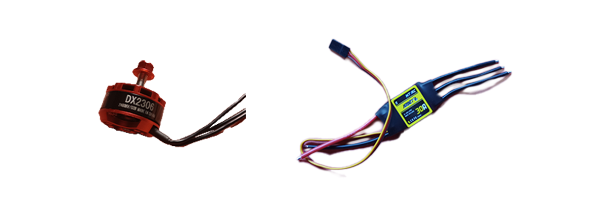
- March 12: ESC/rotor/motor assembly v2 and battery inventarized.
- March 14: ESC/rotor/motor assembly v2 soldered and prepared.
- March 14: Power Distribution Board (PDB).
- March 15: Functional test succeeded: all ESC's + motors working properly.
- March 15: Battery needs additional XT60 connector pieces.
- March 16: Battery soldered on XT60 connector pieces.
- March 16: Functional test succeeded: battery working properly.
- March 17: Functional test succeeded: transmitter-receiver working properly.
- March 17: Cleanflight configuration setup adjusted.
- March 23: Functional test failed: inbalanced motors, standard value too low (±1200).
- March 26: Functional test failed: insufficient propulsion.
- March 26: Battery completely drained: net output voltage ±5V. Charging station refuses/enters safety prevention.
- March 26: Charging station manipulated to NiCd-charging settings. Battery charged.
- March 26: Functional test succeeded: motors operational, balancing incorrect. No floating state.
- April 1: Resoldered ESC's.
- April 12: Flight test failed: Crash after immediate tilting. No floating state.
- April 13: Flight test failed: Wron. No floating state.
- April 15 Flight test failed: Crash. No floating state.
- April 16: Flight test failed: Wobbling causing crash. No floating state achieved.
- May 10: Revised configuration flashed with rotated gyro-orientation.
- May 10: Flight test succeeded: Correct balancing and floating state. Finetuning required.
- May 16: Practise flight.
- May 20: First draft for mp3 player functioning.
- May 24: Practise flight resulting in burned ESC 3 and motor 3.
- May 25: Independent setup for mp3 player functioning.
- May 26: Mp3 setup functioning on-drone.
Goal and strategy:
The goal of this project is to get more familiar with electronic hard- and software and control a setup of a drone that can be applied in agritech contexts to scan, monitor and/or intervere in a growing environment. Though there is not a fixed desired outcome of this project I try to create a system that can be changed/adapted to a certain extend.
Process
When showing the draft of the circuitry Eduardo provided some reference materials and suggested to swap the Arduino Uno with a Naze32 flight controlling unit which he had available to apply in this setup. He explained that the Arduino would largely limit the flight functioning and picking a more common board would ease the customization in case of later configurations for more specific applications.
At first the ESC-motor combination did not function properly. I ran the assembly through a 5 VDC power supply but only got a brief momentary action. Betaflight did not support the older firmware of the Naze34 flight controlling board. When ran through a different configurator called Cleanflight, the movement of the gyroscope gave correct feedback on all three (X,Y,Z) axles but still without activity of the motor. Basically all components needed to be inventarized before running any first functional test.
The parts seemed to be in-tune which each other compared to the reference setups I had. However I still wasn't sure about the wiring and connections. The reason for this is because the battery had 12AWG (international index for wire diameters) wire, the motors 20AWG and ESC's 16AWG. These differences could physically be evened out with either soldering or connectors but could cause some strange transistions in electric resistance.
Main focus at this point is to get a calibrated connection between the receiver and transmitter with the battery in place. The connector of the receiver was wrongly connected at first causing no processing of the transmitter's signalling. With this corrected, the joystick- and switches movements were being interpreted by the receiver, configured through the Naze32 and fed by the ESC's to motor movement.
To get a proper functioning and controlable setup the motor should have enough propulsion to carry itself and take off. To reach this state I had to go through a series of test flights and see how to interact with the controls.
Applications:
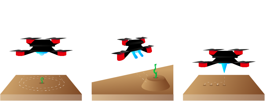
There are lots of additional uses and variations for it which are yet to be explored. During a field visit at Aurora del Camp in El Masnou we discussed some of these potential use cases with Gillad. He imagined they could have effect in keeping birds at distance since they caused over 3000€ in annual crop damage. I proposed to create a setup Big thanks to Eduardo and Adai from Fablab BCN.